


- Systems
Benefits of digital Modbus communication compared to analog signal transmission


Vaisala USB cable can be used with Raspberry Pi.


Although analog probes and data collection technology have a lot to offer, they also present several risks. Modbus is a digital communication protocol that overcomes many of these issues. In this first blog post in a series of three about Modbus, we introduce this established fieldbus protocol, discuss its benefits, and explore how it is implemented in Vaisala devices.
What is Modbus?
Modbus was developed by Modicon in 1979 and is one of the oldest fieldbus protocols available. The initial intention was to create an open protocol; thanks to the success of this strategy Modbus is now seen as an industry-standard protocol and supported by most programmable logic controller (PLC) brands because no licenses or proprietary hardware are needed and it’s free to implement a control system. Vaisala products use either Modbus RTU, which is built on the RS-232 or RS-485 protocol or Modbus TCP/IP, which uses an Ethernet network. One potential downside of Modbus especially in serial line communication (RS-485) is that if you have a multi-vendor configuration that uses instruments from different manufacturers in the same network, there may be some compatibility issues between the different brands.
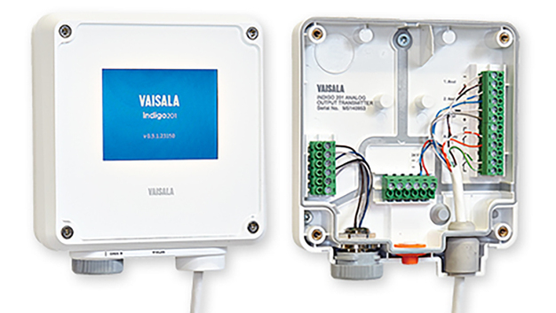
The Vaisala Indigo201 analog transmitter
The Vaisala Indigo platform is used extensively in a wide range of challenging industrial applications. The product consists of an analog data transmitter attached to an intelligent, interchangeable probe that measures variables such as relative humidity and temperature, dew point temperature, carbon dioxide or hydrogen peroxide concentration. All measurements and calculations are performed digitally by the Indigo compatible probe, which is also capable of operating as a standalone unit without a transmitter. The probe passes the data on to the transmitter, which then sends it to a PLC in analog form.
The issue with analog signal transmission
Typically, a digital humidity probe, in this case, a Vaisala HMP3, has two sensors – one that measures temperature, such as a PT100 sensor, and one for relative humidity, for example, a Vaisala HUMICAP® sensor; in reality, these sensors are actually measuring changes in resistance and capacitance respectively. The probe converts the analog signals into digital data, makes the necessary calculations for temperature and relative humidity, and sends the accurate digital data to the Indigo201 analog transmitter. The transmitter then converts this signal back into analog form to be transmitted via analog cabling to the PLC, where it is once again converted to digital data for processing and storage.
As might be expected, converting the digital data into an analog form in the data transmitter and then back to digital in the PLC or other control system will introduce additional error sources. Ensuring accurate measurements is important from both a quality and regulatory perspective, and one way to minimize errors is to use digital communication. This is where Modbus comes in.
The advantages of Modbus
The same probes that can be used with the Indigo201 are also compatible with the Modbus RTU digital communication protocol. Because Modbus uses digital communication, in addition to relative humidity and temperature the probe can also be used to measure many other parameters including dew point/frost point temperature, absolute humidity, mixing ratio, wet-bulb temperature, and enthalpy, as well as additional information such as device status, serial number, and security hash. Allowing the Modbus master to check the security hash status allows you to ensure that the sensor hasn’t been tampered with and that the probe configuration has not been altered. It’s also possible to connect multiple probes to the same network; with an analog system, this would require a substantial amount of additional cabling and (I/O) modules to be installed in the PLC system. Modbus also reduces the risk of data errors by minimizing conversions between analog and digital, making it a great option for digital data transmission.
Transmitter is not just an analog to digital protocol converter
Although the Indigo compatible probes can be used as standalone measurement instruments, the best usability is often achieved together with a transmitter that offers a local user interface, display, different power supply options, and some of them with the advantages of digital communication. The Indigo202 transmitter provides the same Modbus RTU as the probe and the Indigo500 series transmitters communicate with Modbus TCP/IP-protocol.
Getting set up with Modbus
In the second in our series of blog posts on Modbus, we show you how to get started in a short introduction video that covers testing and configuration. We then go on to discuss prototyping and commissioning.
You can watch the short video here.
Build a prototype
Now that you’ve established that your computer and probes are talking to each other, you can connect them to your systems, so the next step is typically to build a prototype. For instance, you can do this using the Raspberry PI platform, which has USB ports for connecting Vaisala USB cables to test Modbus RTU and a LAN port for testing Modbus TCP/IP. The recommended languages are Python or Node-RED, both of which have free, open libraries (PyModbus and Node-red-contrib-modbus respectively) for communicating with Modbus.
While the Raspberry Pi platform is fine for testing, it’s not suited to an industrial environment, so you’ll probably need something more robust such as a PLC; depending on the model, the PLC may also require a separate module to provide RS-485 access.
Check your Modbus communication settings
To avoid communication issues, all devices in a network should use the same communication parameters and have unique Modbus device addresses, which must be set manually. The Modbus protocol uses function codes to exchange values between the Modbus master and the slave devices. For instance, the master can communicate the process pressure value to the probe, which can then use this information to take a more accurate humidity reading. Because Modbus registers are vendor-specific, the values may be found at different addresses depending on the manufacturer. Another potential pitfall to watch out for is that while Modbus numbers the registers starting from one, some Modbus systems use values that start from zero, meaning that some trial and error may be required. To help with this, Vaisala products come with test registers for integer values, floating points, and text strings.
Commission your new system
Here is a checklist of things to keep in mind when carrying out commissioning:
– Communication settings need to be correct
– Wiring must be correctly connected, with a signal ground that passes through its own wire in the cable, not the chassis of the device
– All slave addresses must be unique when using multiple instruments
Once these initial checks are complete, you can test whether the slave devices provide an answer to the Modbus query. If there’s no answer, try to get the communication working with another Modbus master such as your PC and service cable. This can help to identify the source of the problem. The next question to consider is whether you got the expected response. If not, you can check the test registers to ensure that you’re requesting information from the correct address and, in the case of float value, that the endianness is correct.
Communicating with a PLC
Every PLC brand has its own way of implementing function blocks and libraries for Modbus communication, so it’s not possible to give any generic instructions on how to build the communication logic. However here are two cheat sheets for building successful communication with two widely used PLCS:
Allen-Bradley Micro820 Modbus RTU Guide
Siemens S7-1200 Modbus RTU Guide
That’s it – you’re all set up
Once you’ve carried out any necessary corrective actions, you should then have the expected response, meaning that from now on the system will respond correctly with no signal transmission errors. However, if you’re still having issues after going through these initial steps it’s probably time to call the manufacturer of the slave device to investigate the issue.
An introduction to Vaisala viewLinc
In the third and final blog post in this series on Modbus we take a look at Vaisala viewLinc, a digital monitoring system that’s especially suited to Modbus due to the communication protocol’s ability to transmit data digitally. Because analog to digital conversion only occurs at the point of measurement, using viewLinc with Modbus allows for extremely accurate collection and storage of data.
Typical viewLinc applications
Vaisala viewLinc Continuous Monitoring System is often used in regulated environments, for instance with pharmaceutical products and medical devices. Adhering to the regulatory requirement to use a separate redundant system for monitoring allows users to demonstrate that processes such as drug storage have been performed within the required specifications. Unlike programmable logic control (PLC) platforms, viewLinc isn’t a control system – it is used to monitor for data collection and storage, send alarms whenever any measured values fall outside of the specification and provide robust historical data to demonstrate that process values have been maintained within the required limits.
In these types of regulated environments, viewLinc is generally used to monitor temperature and humidity in manufacturing and storage areas, where heating, ventilation, and air conditioning (HVAC) systems are typically used as control systems. As these systems don’t have enough sensors to provide the detailed information required for monitoring, viewLinc performs this role. Being an entirely digital system, viewLinc doesn’t deal with any analog data and all analog to digital conversion is carried out by the sensors at or near the point of measurement, from which point the digital data can be accurately transmitted and processed. As digital communication has become the norm for monitoring systems in life sciences environments, long analog cables, and numerous thermocouple networks are now largely a thing of the past.
Using viewLinc for non-digital applications
Although digital data is generally preferable in highly regulated environments, viewLinc also has a universal data logger that accepts analog inputs, allowing facilities to use specialized legacy instruments or older equipment that only outputs analog values for parameters that aren’t otherwise offered by Vaisala’s data loggers. This ability to accept almost any measurement is also beneficial where the parameters being measured minimize the error risks associated with loop calibrations or calibrating in the field. A good example of this in viewLinc is differential pressure measurements, which are often used in cleanrooms; high pressure is used in these areas to ensure constant airflow into the dirtier parts of the facility, keeping the area clean by preventing particles from flowing upstream.
Differential pressure measurements are taken in a panel housed near the data logger, allowing for short wires that reduce the impact of wiring on the analog signal and therefore minimize errors. It’s easy to integrate stable, reliable calibration equipment in the field for differential pressure, and this is the exception rather than the rule in this sense. For cleanroom measurements where it’s inconvenient to perform a loop calibration due to longer wires or issues with your calibration reference standard, or where the device signal is too complicated for an analog signal, digital is more helpful. One example of this is particle counters, which are important for determining how clean the room is.
Connecting viewLinc with Modbus
Particle counters provide complicated process data that can’t be easily conveyed with an analog signal and is therefore much better suited to a digital signal. This digital data is ready to travel, so there’s no need to convert it to analog and back again – it just needs a direct digital pathway to the viewLinc system, and the pathway we use is Modbus. To make it easier to convert a Modbus device to viewLinc, we’ve created a library of templates within the system – for example, complicated devices such as particle counters can be added by simply selecting the correct template. It’s also possible to create and save new templates, which you can then use again and again.
Because digital communication remains accurate over long distances, it decreases the number of calibrations needed, increases calibration accuracy, and allows you to simply send the data logger to a calibration lab and replace it with a unit that’s pre-calibrated for your specific process. The viewLinc system has analog sensor capability, but this is only useful in cases where there’s no other option. For this reason, viewLinc uses the Modbus communication protocol wherever possible.
![]()
Vaisala GmbH
Rheinwerkallee 2
53227 Bonn
Germany
Phone: +49 228 249710
Fax: +49 228 2497111
email: vertrieb@vaisala.com
Internet: http://www.vaisala.de


