Dipl.-Ing. Helene Schöngruber Bsc, Dipl.-Ing. Christoph Lhota
Turned upside down
New cleanroom concept for high temperature applications
High temperatures are not wanted in cleanrooms, however, in the injection molding process they are unavoidable. Research on the influence of mold tem-perature by laminar clean airflow underlines the significance of this subject and simultaneously lays the foundation for a completely new cleanroom concept with reversed airflow. The first industrial installations promise much potential for even higher cleanroom quality.
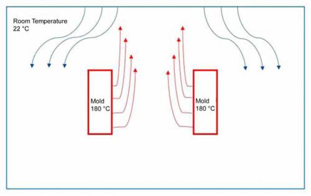
For injection molding of thermoplastics, the resin pellets are heated in the barrel until they have reached a viscous or liquid state and are then injected into the temperature-controlled mold. The temperature of the mold is a material-specific parameter with a direct influence on the process and in particular on the cycle time. The mold temperature also influences the air-flow, which is relevant to the injection molding process in cleanrooms. The hot air radiated by the mold rises and therefore moves in the opposite direction to the cleanroom airflow which conventionally runs from top to bottom (Figure 1). As the temperature rises, the particulate load increases which puts the cleanroom quality at risk. Uneven airflow in the mold area can cause particle deposits on the parts because there is not enough clean air coming in to re-move the contamination.
Influence measurable at 40°C
It was investigated for a thesis from which mold temperature use of a conventional filter fan unit (FFU) or laminar flow box is ineffectual [1]. The experiments were carried out in the cleanroom of the injection molding machine manufacturer ENGEL AUSTRIA in Schwertberg, Austria. The LMP type laminar flow modules were provided by Max Petek Reinraumtechnik (Radolfzell, Germany). They were developed in the size used specifically for injection molding machines.
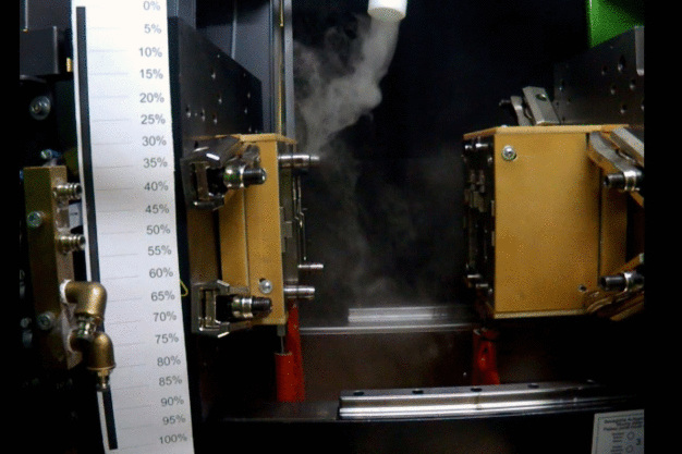
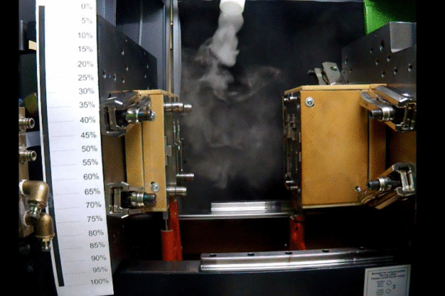
Two system conditions were used for comparative purposes: one with normal cleanroom air-flow, and the other with the mold and ejector area encapsulated with an LMP. In both series of experiments, mist was added from above to the mold area to make the airflow visible for both systems. Mold heats were also held constant across both experiments.
It was established with the simple experiment that without an additional laminar flow module the mold temperature of 40°C already influences the flow of clean air through the mold area. This outcome shows how important this research work is because such a low mold tempera-ture can only be used for very few applications.
The LMP was used to achieve an even more constant flow from top to bottom. The air veloci-ty was set on 0.45 m/s in accordance with the EU GMP Directive. The mist tests in this en-capsulated configuration were recorded in a video. The still images clearly show that a con-stant airflow no longer prevails and turbulence occurs from a mold temperature of 90°C and above (Figure 2). The turbulence occurs primarily directly after opening of the mold; the air-flow settles again after four seconds and the flow through the mold becomes constant again.
The same measurement was repeated at a mold temperature of 140°C (Figure 3). Here four seconds did not suffice to disperse the turbulence. At this high mold temperature, the com-plete air in the mold area is very hot, and particles are emitted in increased number. An ade-quate laminar flow can only be shown again at an increased air velocity of 0.8 m/s.
Mold opening speed a further adjustment parameter
In addition to temperature, the mold opening speed also has an influence on the airflow. The airflows were investigated at opening speeds of 1100 mm/s and 220 mm/s. The tests showed that a slow movement of the mold mounting platen causes less turbulence than very fast opening of the mold. When, however, the extremes were tested, it was shown that excessive-ly slow opening intensifies the air turbulence as the air between the mold halves heats up again in the long time of mold opening. In contrast to this, extremely fast opening can stabilize the airflow so that the mold and injection molded parts are constantly exposed to clean air. To depict these extreme speeds, mold opening times of 12 and 3 seconds were investigated. The optimal opening speed for the purposes of cleanroom reliability depends in each case on the manufacturing process and the mold. In practice, however, the flow effects cannot always be considered adequately when it comes to setting the opening speed. The medical technology sector is also subject to strong cost pressure and cycle time is a decisive factor in profitability.
The challenge of liquid silicone rubber
The previous experiments established an important baseline for further consideration of injec-tion molding processes in cleanrooms. The objective of a second thesis was, building on the above, to develop approaches on how to ensure a high class of cleanroom at high mold tem-peratures [2]. In order to be able to make assertions for extreme temperature conditions as well, further experiments were not conducted with thermoplastics, but with LSR (liquid silicone rubber). A special aspect of liquid silicone rubber is that the material is, unlike thermoplastics, cooled in the barrel, while significantly higher temperatures of 180°C prevail in the mold. Only at these high temperatures can LSR vulcanize and crosslink. In addition to the high mold tem-peratures, a further complicating factor is the fact that LSR outgasses during processing. At high temperatures silane is released, which can be seen as a cloud with the naked eye. These volatile components of the liquid silicone rubber are an additional contaminate to the clean-room and in the course of production can quickly exceed the limit defined for the respective class of cleanroom. The cleanroom in the ENGEL technology center was set up in ISO Class 7 for the experiments for the thesis. Particle measurement after just a few cycles already showed an excessively high concentration of particles with a diameter of 0.5 µm.
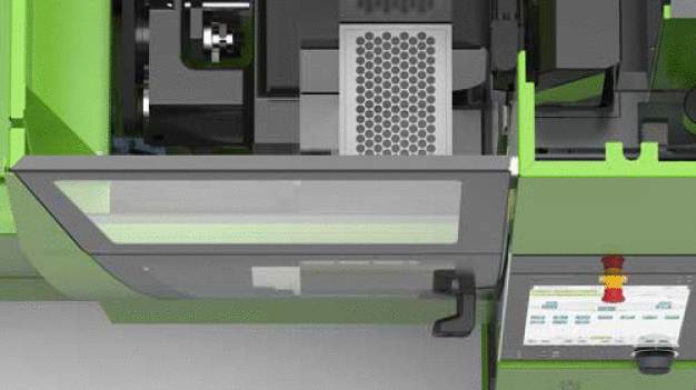
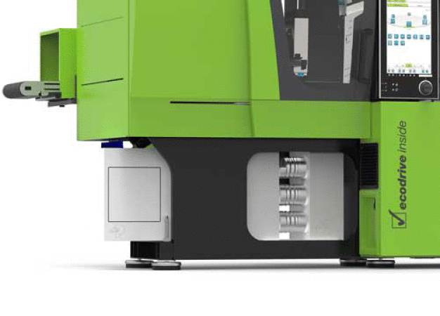
A first approach to solve this problem consisted of encapsulating the mold area with an LMP in order to vaporize the silane cloud. Unlike normally, however, the clean air was not intro-duced into the mold area from above, but from below. The extraction downwards normal in cleanrooms up to this point in time was to be used to remove the silane particles. Although this experimental setup was unsuccessful, a lower concentration of particles was measured than in the previous measurement, even though it did not yet conform to the requirements of the cleanroom class ISO 7.
Simulation confirms empirical research
The idea of reversing the airflow was then implemented consistently in a second step. The clean air was not only passed from bottom to top, but the mist cloud was also sucked out of the mold area upwards (Figures 4 and 5). The thermal makes the mist cloud disperse and gain speed quickly.
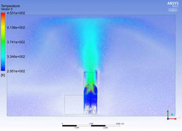
A simulation of the experimental setup (Figure 6) was used to corroborate the test results using ANSYS software version R16.2 Academic. The calculations confirm the good result of the tests in the technology center and make it possible to predict the behavior when changes in the environmental conditions occur.
Max Petek Reinraumtechnik has developed a cleanroom solution with reverse laminar flow on the basis of these results. The air is sucked upwards out of the mold area.
First industrial system built
The results of the two theses cited in this article clearly show that the influence of mold tem-perature on reliable cleanroom operations cannot be neglected. The laminar flow is already disturbed at mold temperatures above 40°C. A mold temperature of 110°C was established as limit for a conventional clean airflow from top to bottom (without additional laminar flow module). Both empirical measurements and simulations prove that the particle load can be minimized by reversing the flow of clean air.
ENGEL AUSTRIA and Max Petek Reinraumtechnik have already implemented the results of this study industrially. The new solution has the potential to become standard for high temper-ature applications.
References
1. Denisa Costas, Analysis of the impact of process temperatures on the cleanroom airflow during the injecting moulding of medical grade high performance thermoplastics, thesis for the degree course in Medical Engineering at the University of Applied Sciences Upper Austria, Linz, Austria, 2015.
2. Helene Schöngruber, Identification and analysis of thermal flux in the cleanroom during liquid injection moulding, thesis for the degree course in Medical Engineering at the University of Applied Sciences Upper Austria, Linz, Austria 2016.
ENGEL AUSTRIA GmbH
4311 Schwertberg
Austria
