


- Translated with AI
With expertise for the optimal feeding system
Correct system design ensures high plant availability - The supply analysis and its influencing factors
Smartphones, cars, or computers: product life cycles are becoming increasingly shorter. Nevertheless, every new product also requires the appropriate production equipment, which must be planned and implemented even more quickly, such as the assembly line including feed technology. Many pieces of information and parameters must be considered to achieve an optimal result in the interaction of various components for a smooth process flow. Long-standing experience, innovative strength, and standardized modules for quick availability qualify Amberger DEPRAG SCHULZ GMBH as a global player in the feed technology market. To explain the various backgrounds and interrelationships of the feedability of fastening elements and their optimal design, Thomas Lederer, application expert for screw technology and automation at DEPRAG, answered some questions in an interview.
Question: The provision of fastening elements, such as screws, via feed hose is the preferred method of feeding, as it currently offers the highest process reliability and the shortest cycle times. Whether a feed with hose is possible is evaluated by DEPRAG experts through a feedability analysis. How is such an analysis conducted considering all eventualities?
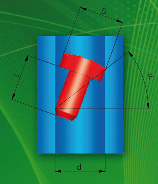
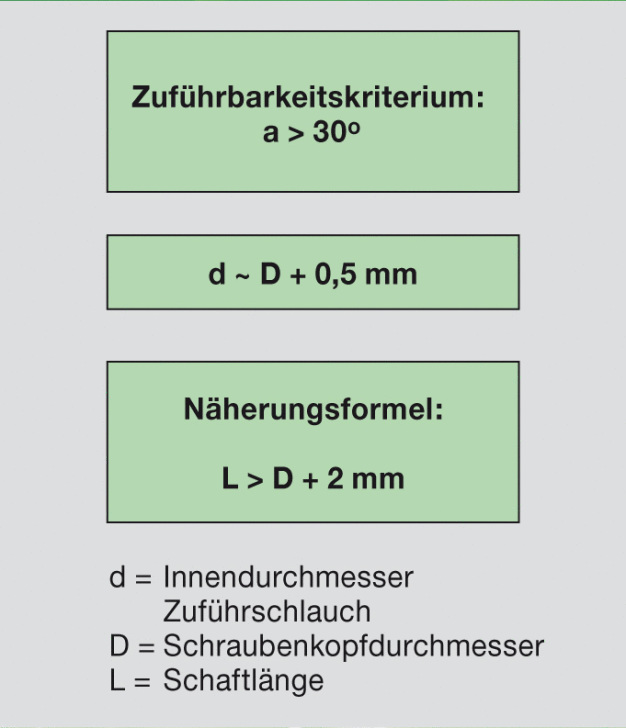
Lederer: The key question is: Is automatic feeding of screws via hose possible, and if not, can a feed via hose still be realized through a simple change in screw geometry? One way to check feedability over a hose is by using an approximation formula (see Figure 1). This allows preliminary determination of feedability. The formula calculates the ratio of screw length to screw head diameter and from this, the possible angle of inclination of the fastening element within the feed hose is derived. If the angle result is borderline, our specialists come into play. Using a screw dimension sheet, it is possible to determine the actual inclination of the screw in the appropriate feed hose via CAD inspection. If the result is negative, small changes in screw geometry, such as reducing the head diameter or lengthening the screw shank, can often achieve feedability. If changing the screw dimensions is not possible, the pick-and-place method offers an alternative. This feed technology positions the fastening element in a clearly defined position and thus makes it available for pickup by the screwdriving tool using vacuum, gripping system, or magnetism. Additionally, this feed technique via pick-and-place also allows the provision of other parts, such as O-rings or labels.
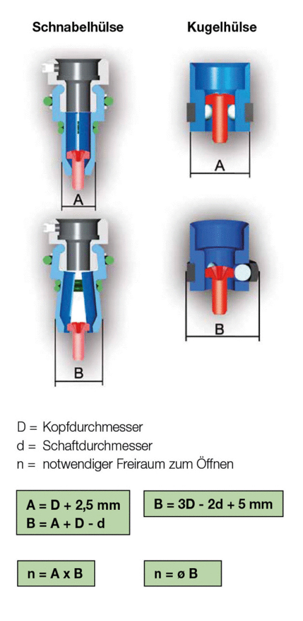
Question: After the fastening element has been fed via hose or pick-and-place method, it must now be positioned over the screw location. This is done with a screw holder, which can be designed as a ball or a jaw chuck. What specific criteria influence the choice of the chuck, and what solutions are available for extreme cases, such as very deep screw locations?
Lederer: The decisive criteria for the screw holder are the available space conditions on the component. The jaw chuck requires space to open the jaws, whereas the ball chuck provides a centering possibility in the area of the screw location to ensure a stable position for screwing. The type of screw holder is only determined after thorough analysis to find the optimal solution for maximum process safety and ergonomic work. For example, if a deep screw location is present and the screw must be guided through a depression, it can happen that the screw falls into the bore and misses the core hole. It then tilts and blocks the overall process. To counter this problem, which we call "free fall," we use the DEPRAG Feed Module. Using a vacuum-based screw holder, a corresponding feed stroke, and a guided vacuum tube, the screw is transported to the deepened screw location until processing.
Question: Regarding space conditions – if necessary, screw templates are used for better positioning of the ball or jaw chucks. This prevents slipping on inclined housing geometries and increases process reliability. Does the repeated positioning of the template affect the cycle time of the screwing process?
Lederer: Yes, since the screw template must be repositioned and removed for each component change, changes in cycle time are to be expected. However, there is only a potential time loss because each hole in the template has conical guide bushes that facilitate the positioning of the ball chuck. As the number of screw locations increases, the time lost during positioning and removal of the template can be compensated for or even shorten the overall cycle time. The use of screw templates is carefully analyzed beforehand, considering all relevant aspects, and implemented only if it has a positive effect on the application. Otherwise, their use is limited to cases where a template is indispensable. This applies, for example, to sensitive components in electronics manufacturing, such as those used in smartphones or automobiles, to prevent damage during screw positioning by the operator.
Question: For the use of multiple feed systems, there are various system configurations – for example, via distributor systems, twin devices with double helix, or a combination of both. What customer benefits do these two variants offer, and what factors influence the decision?
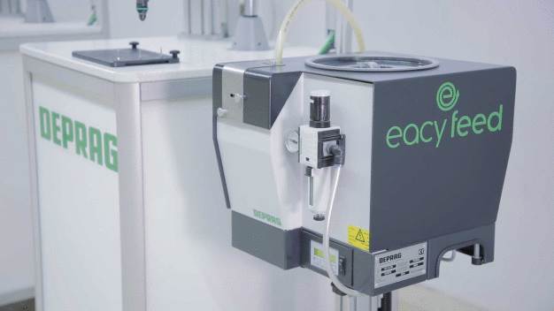
Lederer: The design of feed systems depends on the number of screw systems to be supplied and the production rate. Simple distributors can only individualize, but do not influence the sequence of feeding. In simple terms, they can only supply screw positions with the same demand for screws per unit time. Vibration bowl feeders with double helix, also called twin devices, can operate two screw locations completely independently and thus cover different demands. The DEPRAG eacy feed vibration bowl feeder is available as a twin device. It also offers additional benefits for the user: With eacy feed, energy savings of up to 80% are possible. Moreover, eacy feed is Industry 4.0 capable. Using the standardized, modular DEPRAG components, both concepts of multiple feeding can be combined, allowing us to respond to various individual customer requirements. Our experts calculate the ideal configuration for the desired application regarding the number of screws, cycle time requirements, device needs, and economic factors. The number of outputs can be expanded arbitrarily, but this only makes sense up to a certain extent in the application.
Question: The quality of the screws being fed is an important topic concerning plant availability. Depending on the application, the required purity levels may be higher or lower. How do DEPRAG experts determine the recommended quality level to ensure a cost-effective yet process-safe system?
Lederer: The screw quality according to DIN is 3%, meaning that out of 100 screws, 3 defective parts are allowed. This is often not sufficient for the availability of feed technology. There is no universal value for all applications. Higher quality levels directly positively impact plant availability. First, the optimal purity level must be calculated considering the requirements for plant availability according to VDI 3423. Our feed technology experts determine this by analyzing failure risks to achieve an overall result that is technically and economically optimized and ensures process safety for our customers.
DEPRAG SCHULZ GMBH u. CO.
92224 Amberg
Germany


