


- Translated with AI
Dipl. Ing. (FH) Helmar Scholz
Knowing which way the wind blows
Measuring airflow correctly in the cleanroom

Figure 1: Flow distribution under an FFU

Figure 2: Installation of a sensor under an FFU
 Helmar Scholz, Head of Sensor Development, SCHMIDT Technology GmbH")
Dipl. Ing. (FH) Helmar Scholz, Head of Sensor Development, SCHMIDT Technology GmbH
The measurement of laminar airflow velocities in cleanrooms places the highest demands on the sensors. Choosing a suitable measurement method for accurately detecting even the smallest flow velocities is only the first hurdle. Design aspects such as an easy-to-clean, wear- and drift-free construction are just as important as a precise, application-specific calibration procedure. Accordingly, the application and operation of such specialized sensors also require comprehensive know-how on the part of the operator.
In principle, many physical principles are suitable for measuring airflow, but their technical implementation varies greatly due to the specific boundary conditions of each application, leading to a vast array of measuring devices. However, only a few of these methods or systems meet the special requirements posed by airflow measurement in a cleanroom.
The greatest challenge is considered to be the low airflow velocity range in which the probes are to measure. In the case of laminar flow monitoring and control under a so-called Filter Fan Unit (FFU), which can be regarded as the main application for airflow sensors in cleanrooms, the typical airflow velocity is about 0.45 m/s. This corresponds to a movement of air that a leisurely strolling pedestrian in still air would feel due to their own speed of about 1.5 km/h. It is therefore essential to select a method capable not only of measuring such low velocities but also of resolving them with sufficient accuracy and reproducibility. The thermal method (calorimetric method, measuring the cooling of a heated object) is particularly suitable here, as its maximum sensitivity is in the low-velocity range. Alternative measurement methods such as differential pressure or vortex sensors fail from the outset due to a too high measurement range start, while probe-based systems tend to have their highest sensitivity at higher velocities.
An additional, equally important advantage of thermal anemometers is that they operate completely without moving parts. This means there can be no cross-contamination of the cleanroom air through abrasion or lubricant ingress. The wear-free operation allows for drift-free operation and guarantees high and reliable reproducibility of measurement results over long periods. Last but not least, a GMP-compliant, easy-to-clean, and sterilizable design without undercuts can be realized, which is an essential criterion considering the primary aspect of a cleanroom. Mechanical methods such as paddlewheel sensors are entirely unsuitable for fixed installation in cleanrooms for the reasons mentioned above, and the alternative methods listed earlier also face challenges regarding undercut-free design, especially in the low-velocity range.
However, a good measurement result is not solely determined by choosing the right measurement method; another fundamental aspect is calibration and adjustment of the sensors. Highly precise wind tunnels specifically developed for this purpose are required to characterize and document the sensors accurately throughout their entire lifecycle, starting from manufacturing. In the specific case of laminar flow measurement, two aspects are often underestimated. On the one hand, the low velocities require an extremely quiet environment to achieve the desired accuracy. For example, during calibration in an "open" measurement setup not isolated from the environment, even opening a nearby laboratory or simply passing by the measurement point can cause significant deviations. Therefore, it is advisable that the manufacturer has a closed wind tunnel to minimize environmental influences. On the other hand, an often underestimated or even unknown factor is the application itself, namely measuring a (downward) fall of airflow beneath the filter cover. It must be taken into account that thermal systems, which operate with heaters, inherently generate an upward convection flow due to natural convection, which must be compensated for by the fall measurement. The measurement deviation caused by this can be up to 10% of the measured value at 0.45 m/s, depending on the device. Not only thermal sensors but also paddlewheel sensors are significantly affected by the way the bearing of the paddlewheel is loaded (hanging or lying), especially in the lower velocity range. Most manufacturers, however, only have wind tunnels where sensors are calibrated in horizontal airflow, ignoring the influence of natural convection. Fall wind tunnels, where sensors are calibrated in application-representative conditions, are only available from a very few sensor suppliers.
For proper referencing, the manufacturer of the sensors must have not only an appropriate wind tunnel but also adequate reference measurement technology that allows for norm-compliant verification of airflow measurement at regular intervals. Ultimately, only the use of a laser Doppler anemometer is suitable for this purpose, capable of measuring velocities below 0.05 m/s with high accuracy and resolution.
Understanding how small the measurement quantities are and how easily they can be disturbed by even the slightest environmental influences, one must critically question measurement results in the cleanroom. When installing in a cleanroom, it must be considered that the velocity distribution beneath a filter cover is never homogeneous; especially at the edges of the filter, it is significantly disturbed by the frame (see Figure 1). Therefore, it has proven effective to mount the sensor's measurement point centrally under the laminar flow unit. Regardless of the chosen mounting location, it is important for reproducibility that the measurement position remains unchanged despite all manipulations (e.g., cleaning or sensor replacement). This ensures that the values remain comparable over longer periods. A mounting and installation system that guarantees or at least facilitates positional accuracy is another criterion when selecting the sensor system (see Figure 2).
Even after correctly selecting and installing the cleanroom sensor, errors can still occur. The most common mistakes happen during reference measurements with handheld devices intended to verify the functional performance of the installed sensors, either during commissioning or periodically during operation. If the inherent characteristics of different measurement systems are not taken into account, significant discrepancies can occur between the controlled and controlling sensors. For example, if the reference sensor is a paddlewheel anemometer ("propeller"), it measures the actual molecular velocity of the air, wR, unlike thermal anemometers, which measure a normalized airflow velocity wN based on a specific air pressure pN and temperature TN. To compare both sensor types, it is best to convert the normalized signal of the thermal sensor into the actual velocity wR based on current environmental parameters (air temperature Tact and air pressure pact) using the following formula:
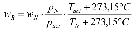
This formula clearly shows that both air pressure and temperature influence the result of thermal anemometers. In a cleanroom, the influence of temperature can be practically neglected due to the stable conditions and operation near the typical reference value of TN = 20 °C. However, the current air pressure can have a significant effect, as the following example illustrates. A thermal airflow sensor for laminar flow measurement under an FFU with a speed-controlled fan was calibrated to a reference value of pN = 1013.25 hPa (standard sea level pressure). If this ceiling unit is operated at sea level in a cleanroom, the actual pressure roughly matches the reference pressure, and the sensor indicates a normal speed wN corresponding to the real speed wR = 0.45 m/s. However, if this unit is installed in the Black Forest at 1000 meters altitude (approx. pact = 890 hPa), the fan motor of the FFU still pushes air with wR = 0.45 m/s through the filter due to the constant rotational speed, but because of the lower air density, the sensor reading, calculated via the above formula, would be:
![]()
Compared to a paddlewheel anemometer, the thermal anemometer under these conditions shows only about 0.40 m/s, a difference of more than 10%. If the user needs the actual velocity as a measurement parameter in the cleanroom, it is advisable to convert the results of the thermal probe using the above formula. Variations in air pressure due to weather changes (typically < ±20 mbar) can be initially neglected. For truly precise measurements, using a pressure sensor that captures all influences of the prevailing air pressure is recommended, and optionally, the ambient temperature can also be measured and included in the calculation.
Flow measurement in the cleanroom is therefore not a trivial matter. Choosing the right measurement system, ensuring reproducible mounting positions, and correctly interpreting the measurement results are essential prerequisites for reliable and robust measurement operation. And one must always be aware of what is being measured: a gentle breeze during a spring walk.
SCHMIDT Technology GmbH
78112 St. Georgen
Germany


