


- Buildings & Rooms
- Translated with AI
Dipl.-Ing. (FH) Polina Bitsch, Dipl.-Ing. (FH) Michael Kuhn, Dipl.-Ing. (FH) Ralf Hoferer
Energy monitoring for cleanroom technology systems
Application example and benefits
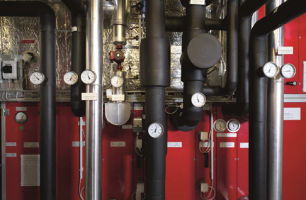

Figure 1: Commissioning of the central data acquisition module in the ventilation control center

Figure 2: DMAIC process as part of a Six Sigma improvement process

Figure 3: Principle of the energy monitoring system used
")
Figure 4: Air technical principle diagram of the system (WRG = heat recovery; MK = mixing chamber; Kü = cooler; BEF = steam humidifier; NE = post-heater; PWT = plate heat exchanger)

Figure 5: Faulty WRG control of the system: simultaneous heating and cooling

Table 1: Overview of the Analyzed HVAC System Variants

Figure 6: Determined energy consumption or energy demand of the examined plant variants, period June - December 2012.
 Polina Bitsch (Project Engineer STZ Euro)")
Dipl.-Ing. (FH) Polina Bitsch (Project Engineer STZ Euro)
 Michael Kuhn (Head of STZ Euro)")
Dipl.-Ing. (FH) Michael Kuhn (Head of STZ Euro)
 Ralf Hoferer (Project Engineer STZ Euro)")
Dipl.-Engineer (FH) Ralf Hoferer (Project Engineer STZ Euro)
Through specialized energy monitoring, time-synchronized measurement and consumption data of air handling systems (AHUs) can be recorded. The optimization potentials identifiable with this, especially in the control technology sector, can lead to significant energy and cost savings without violating GMP requirements. The success of the implemented measures can be demonstrated quantitatively and weather-adjusted.
Initial Situation
A cleanroom operator (sterile production) planned to optimize the mixing air damper control as an energy-saving measure for the existing AHUs. All eight AHUs, previously operated with minimum outdoor air intake, were to be retrofitted with an enthalpy-controlled mixing damper regulation to utilize the so-called "free cooling." Prior to this, the efficiency of the planned measures was to be examined on a representative AHU. For this purpose, the enthalpy-controlled mixing damper regulation was activated on a selected AHU, and measurement data and energy flows were recorded and analyzed using a specialized energy monitoring system (see Figure 3). To evaluate the current state, a simulation model of the AHU with minimum outdoor air intake was created. The results of this investigation (energy savings) served as the decision basis for implementing the measures.
Energy Monitoring for As-Is Recording
The energy monitoring is part of a DMAIC process (Six Sigma methodology) and includes the phases Measure (M) and Control (C) as shown in Figure 2. Energy monitoring of the AHUs refers to a method for recording the energy expenditure for hourly thermal air condition changes in the air treatment unit, based on the analysis and processing of weather data recorded over a selected period and relevant system data such as air temperature, humidity, volume flow, etc. [1], [3]. The energy consumption determined through energy monitoring includes the energy flows for air treatment to achieve the desired indoor air conditions and, if applicable, for energy conversion losses during cooling, heating, and steam generation.
Furthermore, this measurement method allows the detection of control errors, unlike the use of energy quantity meters, because all relevant measurement data are available for analysis.
The necessary system measurement data can be collected and transmitted in various ways. The accuracy of the determined energy consumption is solely dependent on the position and measurement accuracy of the sensors used. Therefore, it makes sense to define all necessary sensors, including measurement locations, before starting data collection, or to verify the suitability of existing sensors. Additionally, a secure and preferably automated data transmission method should be designed.
In the examined existing system, data were measured by sensors already installed on the system and recorded as 10-minute averages using the existing building automation software. Additional sensors were also installed and recorded. The stored measurement data were imported into specialized data processing software and used for energy consumption calculation and fault analysis. The principle of the used energy monitoring system is illustrated in Figure 3.
The AHU under investigation supplies production rooms with 32,000 m³/h of supply air and operates around the clock, as shown in the diagram in Figure 4. The system has the following thermal air treatment stages:
- KVS heat recovery with integrated plate heat exchanger,
- Recirculation air mixing (mixing chamber),
- Cooling with dehumidification (chilled water),
- Steam humidification
- Post-heating
and operates with constant supply and exhaust air volume flows and constant supply air conditions.
The system data were collected from June to December 2012, allowing analysis of system operation during summer, winter, and transitional days. As a side effect, it was found that the system exhibits some control errors. The newly activated enthalpy-controlled mixing damper regulation worked flawlessly but was not coordinated with the heat recovery system (HRG) in the outdoor air duct, supplied by another manufacturer. As a result, the HRG, including the plate heat exchanger, often preheated the air more than necessary, leading to increased cooling energy demand due to the downstream cooling register (see diagram in Figure 5).
To assess the additional consumption caused by control errors, a fault-free current state was simulated using system modeling (Variant A, see Table 1).
System Simulation as a Basis for Evaluation
The effective calculation method for annual energy demand has proven to be system simulation using suitable simulation programs. The system simulation here involves calculating the energy expenditure for hourly thermal air condition changes in the air treatment unit. Actual arrangements and performance data of the air handling components, implemented control functions and sequences, and measured local weather data are used for this.
To compare different types of mixing damper control, another simulation model of the system with constant outdoor air ratio was created (Variant B). An additional system variant was designed to demonstrate potential savings through the optimization of humidity setpoints (expanding the setpoint band by ± 5% r.F., Variant C).
Since changing the damper operation mode has no significant impact on the electrical power consumption of the fans, the comparison of variants did not include the calculation of the system's power consumption. No energy conversion factors were considered; only the useful energy supplied to the central unit was evaluated.
Results
Figure 6 shows that the total energy demand during the measurement period varies from 363 MWh (Variant C) to 570 MWh (current state). The current state exhibits the highest energy consumption due to control faults and unfavorable measurement points for some control-relevant sensors. Considering the current state as 100%, the total thermal energy consumption after correcting the identified faults (Variant A) would be 89%. Variant A, due to its variable outdoor air operation, consumes significantly less cooling energy than Variant B (-17%). However, the energy for humidification increases (+7%). Overall, the enthalpy-controlled mixing damper regulation results in a total energy saving of 49 MWh or 9%.
Comparing the fault-free current state (Variant A) with Variant C shows an additional energy saving of 29% through optimization of humidity setpoints. Variant C proves to be the most energy-efficient operation mode, achievable without costly measures and without violating GMP requirements.
Summary
Based on the described analysis, the enthalpy-controlled operation of the mixing dampers will be activated for all 8 systems, and the faults identified through energy monitoring will be corrected. Additionally, the humidity setpoints will be optimized as described (see [2]). Compared to operation with constant minimum outdoor air, an energy saving of approximately 36% is expected, corresponding to cost savings of about €28,000 per year for the reference system, and extrapolated to 8 systems, approximately €174,000 annually. The energy monitoring will be extended by one year to verify the projected savings.
The energy monitoring conducted within the scope of the project, combined with system simulation, showed that the energy efficiency of the AHUs is strongly influenced by the selected control concept. Energy monitoring not only allows the determination of energy consumption but also the detection of various control errors, such as simultaneous preheating and cooling. Fault correction without investment measures can significantly contribute to energy savings in an AHU system.
References
[1] VDI 2083 Part 4.2: Cleanroom Technology - Energy Efficiency, April 2011.
[2] Bitsch, P. and Kuhn, M.: Energy-efficient dehumidification in cleanroom air conditioning systems. In: Cleanroom Technology 2010 (2), pp. 16-20.
[3] Kuhn, M.: New method for operational optimization of cleanroom air conditioning systems. In: VDI Reports; 2083, Frankfurt 2009, pp. 195-203.
![]()
STZ EURO Steinbeis-Transferzentrum
Energie-, Umwelt- und Reinraumtechnik Offenburg
Badstraße 24a
77652 Offenburg
Germany
Phone: +49 781 20354711
email: mkuhn@stz-euro.de
Internet: http://www.stz-euro.de


