




- Products, devices, systems, plants for applications
- Original text
Choosing an Enclosed Orbital Welding Head for Clean Tubing: C-Series Sizes, Wall Thickness and Access
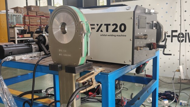
Enclosed C-series welding head with FXT20 power source in a workshop. (Image source: FYID-Feiyide)
A request for a clean-tubing welding system becomes more useful when it identifies the actual tube and connection: for example, 316L stainless steel with a 25.4 mm outside diameter and a 1.5 mm wall, rather than simply “one-inch hygienic tube”. Outside diameter, wall thickness, filler requirements and the space beside the joint determine which equipment configurations merit evaluation.
Enclosed autogenous orbital TIG is one configuration to consider for a suitable tube butt joint. Autogenous means that no filler wire is added. It should not be selected merely because a welding head fits around the tube; the intended joint and the applicable welding procedure must also suit that process. FYID-Feiyide's C-series heads, paired with the FXT20 power source, provide a concrete catalogue example of how these selection boundaries differ by head.
Read the head rating, not just the family range
The C-series catalogue covers outside diameters from 6.35 to 168.0 mm across several heads. That is a combined family range, not the capacity of each individual head. The published standard selection data are:
Enclosed head | Tube outside diameter, mm | Catalogue wall-thickness range, mm
C5 | 6.35–12.7 | 0.5–1.5
C10 | 6.35–25.4 | 0.5–2.0
C40 | 6.35–38.1 | 0.5–2.5
C80 | 12.7–76.2 | 0.5–3.0
C120 | 19.0–114.3 | 0.5–3.0
C170 | 50.8–168.0 | 0.5–3.0
Source: FYID-Feiyide FXT20/C-series specification and current configuration records, checked 27 October 2026. These figures identify catalogue configurations; they do not establish that every material, fitting arrangement or joint within those dimensions has a qualified welding procedure.
For the illustrative 25.4 × 1.5 mm tube above, C10, C40, C80 and C120 include both dimensions in their listed ranges. C5 does not include that outside diameter, while C170 starts above it. This is a preliminary shortlist, not a recommendation to buy the largest or smallest head. The clamping components and physical clearance around the actual joint still need checking.
For another illustrative enquiry, 114.3 mm outside diameter with a 3.0 mm wall falls within the dimensional ranges of C120 and C170. A head's model number is not its exact maximum tube diameter: C120 is listed to 114.3 mm, not 120 mm. Using the actual table avoids that straightforward specification error. These examples are dimensional exercises, not reports of completed customer welds.
Confirm the process and the material
For clean-utility projects using 304 or 316L stainless steel, record the exact material designation and joint drawing. The standard enclosed C-series arrangement discussed here uses no filler wire. If the approved joint requires filler, the purchasing team should evaluate a different process/equipment arrangement rather than treating the C-series diameter range as sufficient evidence of suitability.
The required tube-end condition, fit-up, internal shielding and handling route must come from the project's process requirements. “Enclosed head” does not mean that the finished assembly is automatically qualified for a cleanroom, pharmaceutical system or hygienic service. Those applications need their own acceptance evidence.
Specify the power source and cooling configuration
The FXT20 catalogue lists a 220 V supply with ±10% tolerance and an output-current range of 5–200 A. The output range is the power source's available range, not a recommended welding current for the examples above. Actual current, rotation and other cycle settings require a suitable welding procedure for the joint.
Cooling also varies within the family. The FXT20 power source is air-cooled; the C5 head is air-cooled, whereas C10, C40, C80, C120 and C170 use water cooling. The power source has a water tank and pump for those water-cooled heads.. A purchase specification should identify the actual head, its matching clamps and cooling connections, rather than assuming that every component has the same cooling arrangement.
Check access before selecting a configuration
Provide the straight clamping length beside the joint, nearby fittings and the space available to install, operate and remove the head. A tube within the diameter range can still be unsuitable for a particular head arrangement because of an adjacent elbow, flange or obstruction. An annotated drawing is more useful than an unmeasured photograph.
The equipment proposal should state which head and fixtures address that geometry and what remains to be verified on a representative sample. Tube cutting and facing support the required end condition, but the central selection decision remains the welding process, head and joint.
Technical reference and author
The head-size comparison and configuration details can be checked in the manufacturer's [FXT20 enclosed orbital welding system and C-series head specifications](https://fyid-feiyide.com/products/fxt20-high-purity-closed-chamber-orbital-welding-system-c-series). The source is a manufacturer's specification, not an independent performance test.
April Pei is Marketing Director at Hubei Feiyide Intelligent Equipment Co., Ltd. (FYID-Feiyide). This contribution presents a supplier perspective on equipment selection. It makes no claim of measured productivity, customer results or cleanroom certification.
Hubei Feiyide Intelligent Equipment Co., Ltd. (FYID-Feiyide)
438800 Tuanfeng County, Huanggang City, Hubei Province
China